Longitudinal profiles and cross sections explained
What longitudinal profiles and cross sections of the ground are for, how we measure them and what the architect receives to set levels, access routes and walls.
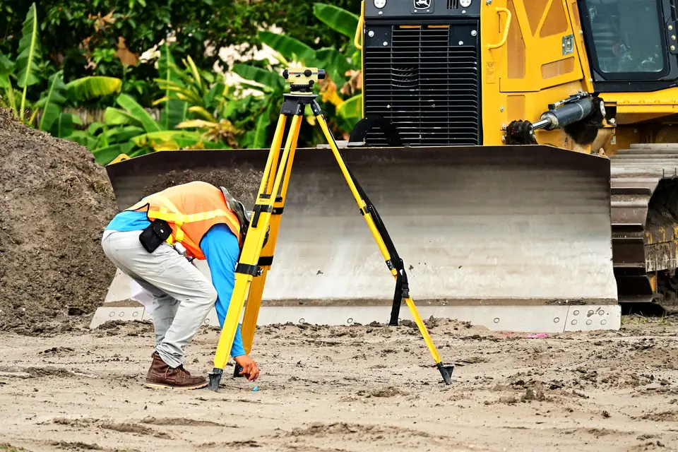
A longitudinal profile is a cut through the ground along an axis; a cross section is a cut perpendicular to that axis. Together they let you see the ground from the side, as if it had been sliced with a knife, and they are the classic tool for designing an access road, a ramp, a pipe run or a wall. When an architect or an engineer asks us for profiles, it is almost always because they are going to move earth and need to know how much and where.
What are profiles and cross sections for?
These are the questions they answer:
- Seeing the changes in height. The rises and falls of the natural ground along the route.
- Setting the design level (rasante). The right gradient and the final level the project will have: a track, a road, a platform.
- Planning the route. Designing access roads, ramps, pipes or channels that have to overcome a difference in level within a maximum gradient.
- Knowing the width of the ground. Cross sections show the ground from side to side at specific points: where there is an embankment slope, a ditch, a wall.
- Calculating earth volumes. How much earth has to be removed (cut) and how much added (fill) to level the ground.
- Designing retaining elements. Walls, foundations, slopes and ditches to prevent landslips or water build-up.
How are they measured?
In the field
We measure ground levels at equal intervals along the axis and at each section. Where the relief has something particular (a sudden change of slope, a terrace, a ditch, the toe of a slope), we densify the data capture. A profile with points every few metres that skips the edge of a terrace is no use for design.
Comparing sources
Depending on the project, the levels can come from several sources: classic surveying, photogrammetry or LiDAR. We check them against one another. Classic surveying gives the highest precision at specific points; LiDAR and photogrammetry cover the whole surface. Comparing them detects errors and poorly represented areas, such as those under dense vegetation.
In the office
The process has three steps:
- Defining the area of interest, the axis and the spacing of the sections.
- Defining the breaklines: terrace edges, the toes and tops of slopes, kerbs. These are the lines where the ground changes slope, and the model has to respect them.
- Creating the contour lines and extracting the profiles and sections from the resulting model.
The case: profiles for an architectural project
On a recent commission, the architect needed the longitudinal profiles and cross sections of the works area to set the design level, plan access routes and service runs, and size the walls.
We measured the levels at regular intervals and densified in the areas with particular relief. We compared those levels with LiDAR and photogrammetric data of the area, defined the breaklines and generated the model and its contour lines.
What we delivered
A plan with the DTM (digital terrain model) and the exact levels of the works area, with the contour lines and the profiles.
What it was used for
The architect had the measured points with their levels and contour lines at a regular interval that represent the shape of the ground with the detail needed for design.
How do you read a profile and a cross section?
In a longitudinal profile, the horizontal axis is the distance along the route and the vertical axis is the level. The existing ground is drawn and, if it already exists, the design level of the project. Where the design level runs below the ground, there is cut; above it, fill.
In a cross section, you see the width: the ground on each side of the axis, the planned platform, the slopes and the ditches. With the cut and fill areas of each section and the distance between sections, the volume is calculated. For large, irregular areas there is a more direct method, which we describe in earthworks control with drones.
Frequently asked questions
How often should a cross section be taken?
It depends on the project and the ground. On uniform ground they can be spaced further apart; where the relief changes, more sections are added. We agree it with the designer.
Can I use the contour lines from official mapping?
For a general idea, yes. To design an access road or a wall, no: their contour interval and their precision do not pick up terraces, slopes or ditches.
What format does the architect receive?
Usually DWG or DXF with the model, the contours, the profiles and the sections, plus a PDF for reference. If needed, also the point file in TXT or CSV.
We measure profiles and sections as part of our topographic surveys and calculate the volumes under volume calculations and earthworks. If you want to know what else the plan should include, see what a topographic plan for the architect includes.
Tags levantamiento topograficoplanotopografiaprecision
Written by Vicent Doménech, geodesy and cartography engineer, chartered surveyor no. 8948.